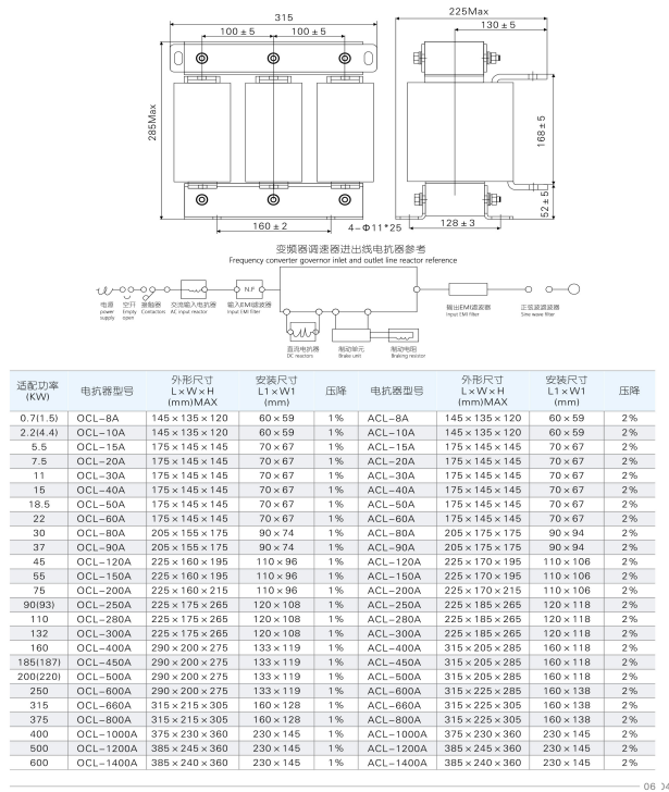
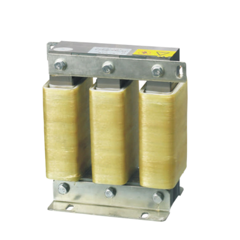
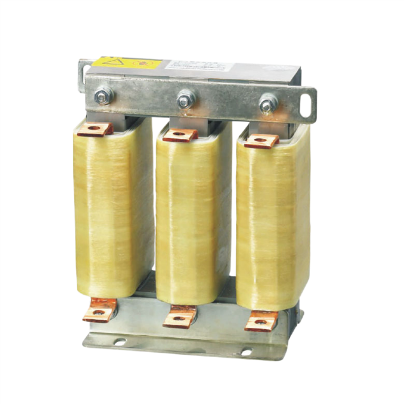
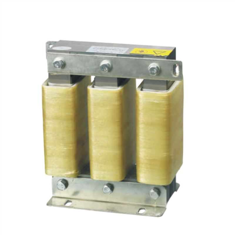
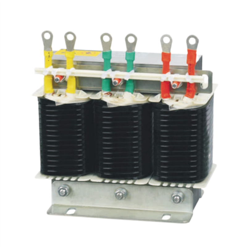
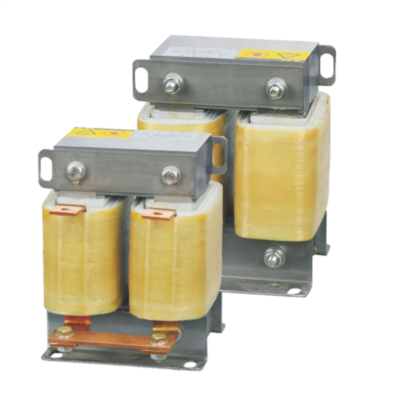
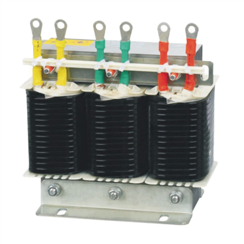
The output filter reactor on the load side of the inverter passe s through the alternating current, and its function is to comp ensate for the capacitive charging current of the long wire. Li mit the rate of voltage rise applied to the motor winding caus ed by the capacitance of the wire (cable), improve the output w aveform of the inverter, reduce the noise of the motor, and im prove the efficiency of the inverter.
1. Reduce the noise of the motor and reduce the eddy current loss. 2. Reduce the leakage current caused by the input higher harmonics. 3. It is used for smooth filtering, reducing transient voltage dv/dt, and prolonging the life of the motor. 4. Protect the power switching device inside the inverter.
The outgoing reactor is used between the inverter and the motor, and when the cable connected between the inverter and the motor is long, it is necessary to add an outgoing reactor only, which can improve the power factor and reduce the motor The temperature rise of the insulating material can filter out the harmonic interference in the cable and improve the service life of the motor.
1. Rated working voltage: 380V50Hz or 660V750Hz 2, rated working current: 3A to 2000A/4°C 3. Electrical strength: iron core-winding 3000VAC/50Hz/5 mA/10s no arc breakdown (factory test) 4. Insulation re sistance: 1000VDC insulation resistance>100M2 5. Reactor noise: less than 65dB (tested at a horizontal d istance of 1 meter from the reactor) 6. Protection level: IP00 7. Insulation grade: F grade or above 8. Product implementation standard: IEC289:1987 reactor GB10229-88 reactor (eqvIEC289:1987) JB9644-1999 reactor for semiconductor electrical drive
